
PRODUCTS
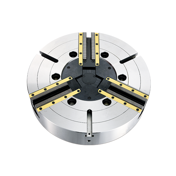
D series (Closed center high precision power chucks)
CLOSED CENTER HIGH PRECISION POWER CHUCKS
HYDRAULIC CHUCKS
Application
Lathe
Milling Machine
Grinding Machine
Milling Machine
Grinding Machine
Features
- Install side strips and chips cover sealed base jaw to prevent chips and coolant ingress.
- Adapter Plates can be selected.
- The base jaw is lower than the body surface and can be used for multipurpose.
- Alternative spindle adaptors: ASA or DIN adaptors can be supplied as requested.
| Model | Adaptor | Plunger Stoke(mm) | Jaw Stoke [Diameter] (mm) | Max.Push Force (kgf) | Max. Gripping Force(kgf) | Max. Hydr. Pressure (kgf/cm²) | Max. Speed (r.p.m.) | Weight (kg) | Moment Of Intertia (kg.m²) | Cylinders | Hard Top Jaws | Soft Top Jaws | Gripping Range (Ømm) |
|---|---|---|---|---|---|---|---|---|---|---|---|---|---|
| D340 | A15 | 57 | 18.5 | 18354 | 32630 | 42.75 | 600 | 650 | 83 | TC25060 | PD1-40-1 | PE1-40-1 | ø112~ø1000 |
| D340 | A20 | 57 | 18.5 | 18354 | 32630 | 42.75 | 600 | 642 | 81 | TC25060 | PD1-40-1 | PE1-40-1 | ø112~ø1000 |
If the dimension and specifications change, please take the confirmation drawing as standard.
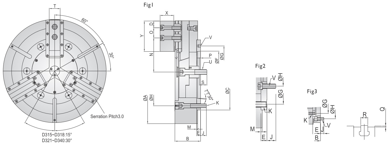
| Model | Adaptor | A | B | C | D | E | F | G | H | J | K | M | N (max) | O (max) | O (min) | P (down) | P (up) | Q | R | S | T | U | V | X | Y | Reference Drawing |
|---|---|---|---|---|---|---|---|---|---|---|---|---|---|---|---|---|---|---|---|---|---|---|---|---|---|---|
| D340 | A15 | 1000 | 180 | 520 | 80 | 27 | 285.775 | 330.2 | 463.6 | 51 | 6-M24 | 8 | 345 | 300 | 60 | -44.5 | 12.5 | 2 | 25 | 60 | 85 | M36*4P | 6-M24 | 88 | 180 | Fig2 |
| D340 | A20 | 1000 | 180 | 520 | 80 | 25 | 412.775 | 463.6 | 463.6 | 55 | 6-M24 | 8 | 345 | 300 | 60 | -44.5 | 12.5 | 2 | 25 | 60 | 85 | M36*4P | 3-M16 | 88 | 180 | Fig1 |